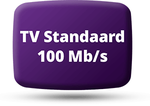
Roganti's Inclinometer
Diagram of Inclinometer (12KB)
1. Theory
Introduction:
The
inclinometer is a unidirectional sensor using a capacitive transducer.
The output is a variable square wave
which is proportional to the angle. The dielectric used within the transducer
is chosen to provide dampening
by reducing oscillations caused by overshooting or shock. Yet still provide
a reasonable reaction
time to angular movements. The dielectric used here is Glycol, which I
purchased in the grocery store,
should be available at the Pharmacy too, and this provides a reaction time
to simulate the circular canals
in the Inner Ear. The single axis sensor has a effective range from +60deg.
to -60 deg with 1deg resolution.
The accuracy is still not perfected, this fluxuates due to it being homemade
versus manufactured,
and hovers around 3deg. The reaction time is suitable to relay the angular
postions for the robot
to react in time. The tranducer is interfaced to a digital oscillator made
with a Schmitt trigger Inverter
gate. The oscillator has an adjustment using a trimmer pot to calibrate
the sensor ouput. The sensor
output is measured via a digital input port on the microcontroller to covert
into the angular position.
A software lookup table is all that's needed if there a concern about computation
speed.
Description
I
have experimented with a Pole balancing robot using various type of homebuilt
Inclinometers and I'll explain briefly here how I solved this. My "pole"
is attached to a base in which I induce the external forces to test the
reaction of the robotic pole. I'll be describing the Inclinometer sensor
which I built to solve the balancing problem, thereafter, you can apply
to this any sort of robot you want. I built this robot using two Inclinometers
to provide an X & Y axis . I know you can simply go out and buy
an Inclinometer, but I couldn't find one cheap enough and suitable to adapt
into my robot.My robot isn't big enough to accomodate most of the commercial
types there are so I resorted to making my own. I'm still working on a
drawing to upload onto my webpage if anyone is curious about how it looks.
It'll be online shortly.
I first experimented with different transducers to detect angular position
similiar to what the others have described. Such as pendulum(inverted joystick)
sensor w/ potentiometer/optical feedback, mercury switches, micro switches,
etc,etc. I found the Inclinometer was a better solution than using an accelerometer
in my project. Perhaps not in yours, but my inclinometer is no more difficult
than interfacing a single input port bit on your microcontroller and having
the software programmed to time the pulse width. The Acceleration functions
can all be done in software. It's not rocket science. At the moment, I'm
still trying to perfect the Inclinometer as far as repeatability is concerned
because it's homebuilt, otherwise it's working as it is and quite accurately
(approx 3deg resolution). Even your ear doesn't have such accuracy.
Now,
what I emphasized in was making it's construction as easy as possible.
I constructed the transducer with clear acrylic plastic so I can view the
response of the electrolytic. I experimented with different types of liquids
to test for dampening, dielectric constant, evaporation, etc. Since the
enclosure for the tranducer is homebuilt the evaporation constant was a
big factor. I'm still thinking about trying some others, even though I
have this working, but it relys on how accessible the materials are. The
electrolytic I use is Glycol, it very easy to get, I find it in the Pharmacy
store, or the grocery store. The dielectric constant is high enough to
let me make the inclinometer fit in approx. 4cc volume space, including
the one chip oscillator. The power is routed to the sensor via the 3-wire
cable. One wire is for the output, then power and ground.
The
shape is cylindrical, 1cm width & 3cm dia., and the transducer probe
is embedded inside. The probe is shaped in a semi-circular pattern and
it's comprised of three elements. The elements are made using 16ga. magnet
wire. They're arranged side by side with the outer two elements being common.
The reason for 3 elements is to take into account for any deviation perpendicular
to the sensor axis. The probe automatically averages any deviation to the
axis through simple parallel circuit law of capacitance. You'll have the
same reading if the sensor is upright or deviated from it's upright position.
This isn't possible with only 2 elements, the capacitance will change.
The oscillator is nothing more than a 1 gate Schmitt trigger Inverter in
a closed loop with a micro-trimmer(multi-turn 100k). The transducer is
wired between the Input and ground. The center frequency of the oscillator
is 1mhz, this is a result of the dielectric in the liquid, plus the components
in order the circuit to oscillate. The capacitance can't be increased any
more than I know of unless there's some other liquid with a higher dielectric
constant AND similiar properties. So, the high frequency output is something
I've been living with. Perhaps a High-Tech liquid but I can't afford it.
At the moment, I have an interface to downconvert the high frequency pulse
in order for my micro (abit too slow for this) to read this. It's simply
a divide counter and through this I can increase the resolution which the
micro can produce.
Anyhow,
that's not the point. The other factor, dampening, was considered to give
the robot a smooth response built into the sensor as much as possible w/o
having to program any more than necessary. The Glycol gives me that, and
with alittle filter subroutine to round it off. The reaction time of the
sensor is quick, no lag whatsoever. The Inclinometer gives me a range of
+/-60deg. I expect anything more than that, the robot is "flat on
it's back" anyway. Not even a person can withold themselves upright
beyond a certain angle w/o falling down.
As
far as Inertia is concerned, this is overcomed due to the inherit nature
of this sensor, much like the semicircular canals in your ear. The inclinometer
performs the same function as this. The robot reacts to all forces applied
to it. If there's a large external force applied to the robotic pole (such
as being pushed), the inertia of the liquid will force it create a counteracting
change in capacitance. This prevents severe oscillations in the robot's
stability. In combination with the liquid dampening, it reacts to the change
in the angular position before it's too late.
The
counteracting change in capacitance from the inertia of the liquid corresponds
to the angle necessary to make the robot lean into the applied force and
thus attempt to balance itself, and it does. The liquid will tend to remain
still (due to Inertia) but slides towards the applied force because of
the cylindrical enclosure and change the capacitance. If there's any change
in the attitude, the sensor will also output the change in angle and the
robot will change accordingly while it's experiencing the shock. The sensor
can also sustain vibration using the Filter software. This software will
cancel the repititious vibrations and avoid the robot from being too sensitive
to this sort of motion.
I
tested this by inducing all kinds forces to try and confuse it, and it
still reacts quick enough to stay upright. When I hold it in my hands and
gyrate it in all sorts of directions it continues to maintain upright.
The next step is to make it free fall rather than me inducing the external
forces. Most of the mechanics are already in place, I just have to attach
the robotic pole to a gimbal on the bottom of it to give it freedom and
watch it go. There may be some info which I forgot to place here, so I'll
try to answer any questions.
2. Construction
Since
this is a homebuilt version , there's still experimentation with construction.
One, especially is how to prevent
the dielectric from evaporating. So far, the transducer has been operational
for approx. 9months before the dielectric evaporated below the threshold
of operation. A suitable container is needed (and not expensive) to produce
similiar results as a hermetically sealed container. Right now, all I use
is a clear plastic material cut up from used boxes, bottles and sealed
with hot glue (not contaminating as superglue is).
3. Materials
Common,
everyday clear arylic plastic material found in consumer packaging. I used
the pill bottles to get the
cylindrical shape for the sensor and flat sheets from the boxes to seal
the ends.
Hot
Glue
Magnet
wire, 16 gauge
74HC14,
Schmitt trigger Inverter
100k
multi-turn trimmer
Glycol
Comments, suggestions, tips are welcome.